ELEKTRONISCHER LASTBEGRENZER
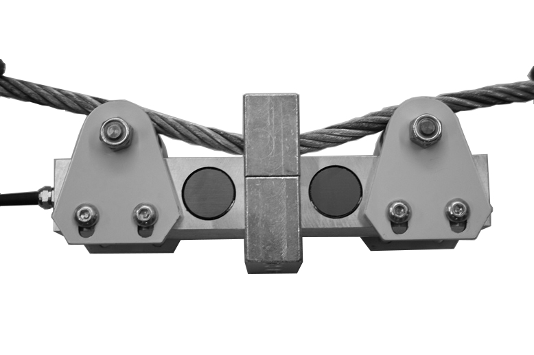
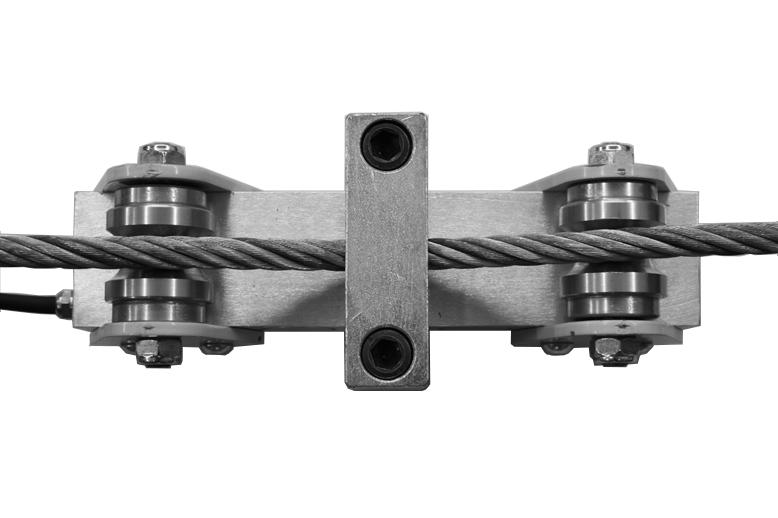
Die Lastbegrenzer der Serie M/G FX sind sehr klein und handlich. Der Körper der Wägezelle ist aus Alu mit hoher Schutzklasse (IP 67) und für Anwendungen in jeder Umgebung geeignet.
Sie werden am festen Seil angebracht und können in wenigen Minuten installiert werden.
Serie limitadores de carga "M / G FX" son muy pequeños y fáciles de manejar, con el cuerpo de la célula de carga de aluminio con un alto grado de protección (IP 67 ) para su aplicación en cualquier entorno.
Se aplican en el extremo fijo de la cuerda y el procedimiento de instalación simple toma sólo unos pocos minutos.
| Mod | FX1 | FX2 | FX3 |
| material | aluminio | aluminio | Ac . INOX |
| Field Cal. (Kg) |
100-3000 | 3001-10000 | 10.001-15.000 |
| Max Rope |
5-18 | 12-30 | 18-40 |
Dim.(cm): |
240x84x80 | 240x84x80 | 240x84x80 |
Gewicht (kg) |
3.5 | 4 | 6 |
![]() Zur Vergrößerung auf das Bild klicken
Zur Vergrößerung auf das Bild klicken


| Material | Aluminium/Edelstahl |
| Nennlast | 3000, 10000, 15000 kg |
| Speisespannung | Maximum 15 V dc (option 24 V dc) |
| Ausgangssignal | Wahlweise 0-10 V oder 4-20 mA |
| Betriebstemperatur | -20 / +70°C (-4 / +158°F) |
| Schutzklasse | IP 67 |
| Größe (mm) | 240 x 84 x 80 mm - 9.4 x 3.3 x 3.1 in (LxWxH) |
| Durchschnittliche Fehler | ≤ 1% des Skalenendwertes |
| Standard Kabellänge | 5 m – 4 x 0,25 (Abschirmung nicht mit dem Gehäuse der Wägezelle verbunden) |
| Typ | GESCHIRMTES KABEL 4C R5 PUR 4X0,25 |
| Länge | 5 m (Bildschirm nicht mit dem Körper der Wägezelle verbunden) |
| Rot | + IN |
| Schwarz | - IN |
| Grün | + OUT |
| Weiß | - OUT |
General precautions to be followed in the installation and assembly of load cells: